
Table of Contents
Key Takeaways
Introduction
What Are Construction Blueprints?
5 Key Features of a Blueprint
Basics of Reading Construction Blueprints
Types of Sheets in a Blueprint Set
Frequently Asked Questions
Key Takeaways:✔ Construction blueprints are detailed plans guiding the entire building process. ✔ Key blueprint features include title and revision blocks, grid systems, legends, and detailed drawings. ✔ Understanding blueprints involves knowing symbols, line types, and scales. ✔ Blueprint sets consist of specific sheets, such as architectural, structural, and mechanical, each tailored to different construction aspects. |
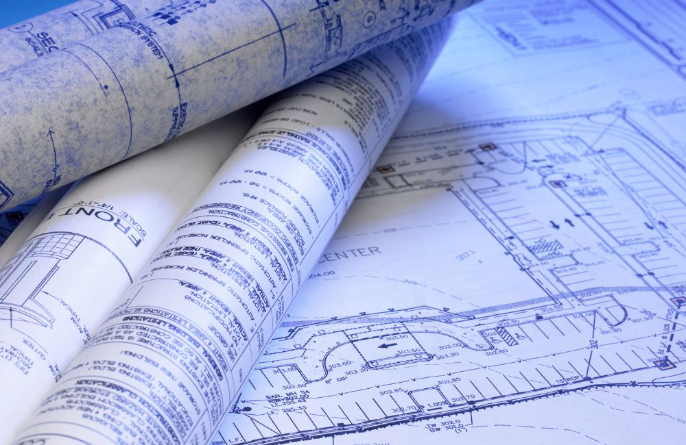
Construction blueprints are the detailed diagrams that guide every step of a building project. They are crucial for ensuring all construction parts are executed correctly and efficiently. Here are the basics of reading and interpreting these essential documents:
What Are Construction Blueprints?
 Construction blueprints are detailed drawings that are the foundation for every construction project. These documents ensure the construction team accurately communicates and executes all aspects of a building’s design. They provide technical information about a project's structural, architectural, electrical, and mechanical elements.
Purpose of Construction Blueprints
Construction blueprints are indispensable in the construction industry, serving multiple critical functions that facilitate the smooth execution and management of any building project. Here's how they play a pivotal role across various aspects of construction:
- Universal Language: Construction blueprints act as a universal language among architects, engineers, and builders, providing a clear and detailed understanding of a project's requirements. This clarity is crucial as poor communication contributes to the failure of 56% of construction projects.
- Guidance for Construction: Construction blueprints are essential for guiding each building process phase, ensuring that all work aligns precisely with the planned architectural and engineering specifications. Statistically, over 30% of project failures are due to inadequate planning and flawed designs, highlighting the crucial role of detailed and accurate blueprints in preventing costly errors and ensuring project success.
- Legal Documentation: Construction blueprints also act as legal documents that can be referenced in disputes or for compliance with local building codes and regulations.
- Record Keeping: They provide a record of the design and specifications, which is helpful for future renovations or troubleshooting building issues.
 5 Key Features of a Construction Blueprint
Construction blueprints are detailed drawings that outline all technical aspects of a building project. They are essential for accurately conveying design intentions and ensuring construction teams have clear guidelines. Here are five key features of a construction blueprint that contribute to its effectiveness:
1. Title Block
The title block is crucial as it contains vital information about the construction blueprint. It typically appears on every sheet within the set and includes:
- Project Name and Location: Identifies the building project and its geographical setting.
- Drawing Title: Describes what the drawing represents explicitly.
- Date: The date when the construction blueprint was produced or revised.
- Architect’s or Engineer’s Name: The credentials and contact information of the professional responsible for the design.
- Scale: Indicates the scale used for the drawing, helping viewers understand dimensions accurately.
2. Revision Block
The revision block is critical in maintaining the construction blueprint's accuracy over time. It records any changes made to the drawing after the initial issue, ensuring that everyone involved in the project works from the most recent version. Details include:
- Revision Dates: When modifications were added to the construction blueprint.
- Description of Changes: A brief explanation of what was altered.
- Initiated By: The name of the person who requested the changes.
3. Grid System
A grid system is used in construction blueprints to simplify locating specific sections of a large or complex drawing. It usually consists of:
- Letters and Numbers: Running along the borders of the drawing, creating a coordinate system (e.g., A1, B5, etc.).
- Reference Points: These allow users to quickly refer and navigate to different parts of the construction blueprint, facilitating effective communication and troubleshooting.
4. Notes and Legends
Notes and legends are essential for clarifying and providing additional details to the visual components of the construction blueprint. They include:
- General Notes: These notes cover broad information applicable to the entire drawing set, such as materials types or construction standards.
- Specific Notes: Offer detailed information relevant to particular parts of the drawing.
- Symbols Legend: A key or legend explaining the meaning of various symbols used throughout the blueprint, which may represent electrical outlets, plumbing fixtures, or materials.
5. Drawing or Plan
The drawing or plan is the primary feature of the blueprint, showing a visual representation of construction or design. These can include various types of detailed plans, such as:
- Floor Plans: Layout of rooms and facilities.
- Elevations: Views of the building from different sides.
- Sectional Views: Cut-through diagrams to show interior features.
- Site Plans: The arrangement of the building and its surroundings on the property.
Basics of Reading Construction Blueprints

Navigating through construction blueprints effectively requires a solid grasp of various fundamental elements. These include understanding the common symbols, recognizing different types of lines, and accurately interpreting scale and measurements. Each component is critical in ensuring the construction plans are executed precisely according to specifications.
Common Symbols and Their Meanings
Construction blueprints are filled with symbols, each representing elements or installations within the structure. Here are some of the most common symbols you’ll encounter:
- Walls: Shown as thick solid lines.
- Windows and Doors: These are indicated by wall breaks, with symbols for opening mechanisms.
- Electrical Outlets: Represented by a circle with lines showing outlet types.
- Plumbing Fixtures: Depicted as straightforward illustrations of sinks, toilets, and showers.
- HVAC Systems: Illustrated with lines for ductwork and icons for vents and units.
Types of Lines and What They Represent
Lines in construction blueprints are not only about boundaries and perimeters; they convey a vast amount of information based on their weight, style, and color:
- Continuous Thick Lines: Indicate structural elements like walls.
- Continuous Thin Lines: Represent non-structural elements such as cabinets.
- Dashed Lines: Suggest hidden features like internal beams or columns.
- Phantom Lines: Denote movable features and possible future modifications.
Scale and Measurements: Reading Dimensions and Sizes
Construction blueprints are drawn to scale, meaning every element is proportionally scaled to fit the page. Understanding the scale is essential for interpreting the actual dimensions and layout accurately:
- Scale Notation: Typically found in the title block, it tells you how much smaller the drawing is compared to real life. For example, 1/4" = 1' means a quarter inch on the blueprint, which translates to one foot in reality.
- Dimension Lines: Marked with arrows and numbers, they show the actual size of elements.
Types of Sheets in a Blueprint Set
Construction blueprints are intricate documents that guide the entire building process, ensuring that various specialists can effectively collaborate. These blueprints are organized into specific "sheets," each coded and classified to streamline construction tasks. Here's an overview of the common types of sheets found in a blueprint set and their functions:
General Sheets (G Sheets)
General Sheets, or "G Sheets" in construction blueprints, are foundational for grasping the project's scope. Key components include:
- Cover Sheet: Provides essential project details and an overview.
- Plan Index: Enumerates all the blueprint sheets in the set.
- Site Plan: Depicts the building's placement relative to property lines, existing structures, and utilities.
Architectural Sheets (A Sheets)
Architectural Sheets, known as "A Sheets," illustrate a building's aesthetic and functional features, which are essential for visualizing the final structure. They include:
- Floor Plans: Show the layout of each floor with details on walls, doors, windows, and fixtures.
- Roof Plans: Provide the roof's design and dimensions.
- Elevations: Display the building's exterior from all sides, highlighting architectural details.
- Detail Drawings: Offer zoomed-in views of specific features such as stairs, cabinetry, and trim.
Structural Engineering Sheets (S Sheets)
Structural Engineering Sheets, or "S Sheets," are crafted by engineers to ensure a building's structural integrity. These sheets detail the core components necessary for stability:
- Foundation Plans: Depict the building's base design, including footings and retaining walls.
- Framing Plans: Show the placement of beams, columns, and other structural elements.
- Load-Bearing Walls: Provide details on walls that support weight from above.
- Reinforcement Details: Include specifications for steel rebar and other materials that strengthen the structure.
Mechanical Sheets (M Sheets)
Mechanical Sheets, or "M Sheets," illustrate the layout and design of the heating, ventilation, and air conditioning units and other mechanical equipment.
- HVAC Layouts: Placement and routing of heating, ventilation, and air conditioning systems.
- Equipment Details: Specifics about mechanical devices like boilers, furnaces, and air handlers.
- Ductwork Plans: Diagrams showing the routes of air ducts and ventilation shafts.
Electrical Sheets (E Sheets)
Electrical Sheets, known as "E Sheets," outline the building's electrical systems, crucial for ensuring safety and efficiency. They include:
- Wiring Diagrams: Routes of electrical wiring.
- Panel Schedules: Specifications of breaker panels.
- Lighting Plans: Locations of light fixtures and switches.
- System Controls: Details on building automation controls.
Plumbing Sheets (P Sheets)
Plumbing Sheets, known as "P Sheets," illustrate the plumbing system's layout, which is vital for efficient water management and sanitation. Key elements include:
- Water Supply Lines: Routes and specs for water pipes.
- Drainage Systems: Layout of waste and stormwater pipes.
- Fixture Locations: Placement of sinks, toilets, showers, etc.
- Gas Piping: Details of natural gas lines, if used.
Landscape Sheets (L Sheets)
Landscape Sheets, or "L Sheets," offer detailed plans for the external surroundings of the building, improving aesthetics and environmental integration. Key features include:
- Planting Plans: Types of plants and their locations.
- Hardscape Features: Designs for paths, walls, and other structures.
- Irrigation Layout: System design for landscape watering.
- Lighting Details: Specifications for outdoor lighting.
Schedules and Specifications Sheets
Schedules and Specifications Sheets provide detailed tables or matrices that outline materials, fixtures, and finishes, which are crucial for maintaining consistency and quality across the construction project. They include:
- Door Schedule: Lists all doors with sizes, types, and hardware details.
- Window Schedule: Specifications for each window, including dimensions and glazing.
- Finish Schedule: Details on wall finishes, floor coverings, and other surface materials.
- Material Specifications: Descriptions of construction materials, including performance criteria and manufacturer info.
Numbering and Classification
Each sheet in a blueprint set follows a specific numbering convention that facilitates easy navigation:
- Discipline Designator: The first letter(s) indicate the type of sheet (e.g., A for architectural, G for general).
- Sheet Type Number: A numerical sheet that specifies the type of information (e.g., 0 for general information, 1 for plans).
- Sequence Number: Additional numerals that show the sheet's order within the set (e.g., A204 for the fourth architectural elevation sheet).
Frequently Asked Questions
What is the difference between blueprints and floor plans?
Floor plans are a part of blueprints, specifically showing the layout of rooms and spaces from a top view, while blueprints encompass all detailed drawings.
How are modern blueprints different from traditional ones?
Modern blueprints are often digital, using software like CAD for precision and ease of modification, unlike traditional hand-drawn blueprints.
Are blueprints required for all types of construction?
Most construction projects, especially new builds and major renovations, require blueprints to ensure compliance with local building codes and regulations.
How do I obtain blueprints for an existing building?
Blueprints for existing buildings can usually be obtained from the builder, architect, or local government offices that manage building records and permits.
Who creates construction blueprints?
Licensed architects or engineers typically create blueprints with the project owner and other specialists.
 Experience Excellence with Claris Design•Build
At Claris Design•Build, we believe in turning your property dreams into reality. Our expert team works closely with you every step of the way, ensuring your vision is brought to life with precision and care. From initial concept to final construction, we provide top-notch services tailored to meet your unique needs. Experience the difference of working with a dedicated team that values quality and excellence. Let’s build something extraordinary together—reach out to us today!